Polaris Software Setup
Polaris Getting Started User Guide
TOPICS
OVERVIEW OF THE USER SESSION IN POLARIS
The POLARIS System is a web-based access control system that uses a secure browser for the User access (i.e., Chrome or Edge, etc.
-
The user (system operator) must have a valid login credentials to open/use the features of the Polaris software.
The system supports the Customer adding hardware programming in the system and configuring reader/door behavior. Also the user can load flash and programming to the panels as well as enroll credentials.
ABOUT THE USER DASHBOARD
-
Polaris will open to your User Dashboard screen when you sign-in through your browser.
-
The User Dashboard is the default landing page when an Operator signs-in to POLARIS.
-
The User Dashboard displays the Operator List (menu tab) by default.
-
You can show/hide the Dashboard Tiles by clicking the Dashboard Show/Hide tile-button.
-
The menu bar allows the User to open different programming screens.
-
-
Notice that your Cluster Group ID is shown under your User Logo/Photo.
IMPORTANT: The same Group ID number must be programmed into every access panel (CPU) in your system, no matter which cluster the panel is in._569x276.png)
USER DASHBOARD > LOGGING-IN WILL OPEN TO YOUR OPERATOR DASHBOARD
SIGN-IN TO POLARIS (START A USER SESSION)
-
Open the Web Browser on your local computer.
-
Enter the POLARIS Web Address into the browser address bar to open the Home page.
POLARIS Browser URL https://polaris.galaxysys.com/login
-
To start a User Session in POLARIS, enter valid operator credentials as follows:
-
Enter the valid email address (system operator username).
-
Enter the valid password
-
Click the [ Sign In ] button.
RESULT: the User Dashboard will open for the system operator that is associated with the Operator Group ID.
.
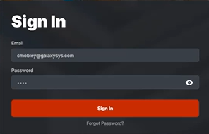
POLARIS: User Sign-in Modal (Login Modal)
-
ADDING HARDWARE IN THE POLARIS SYSTEM
You can add Clusters, Panels, Boards from the Hardware tab.
-
Opening the Hardware tab displays the List of Clusters.
-
Each Cluster has its own ribbon with the hardware stats shown.
-
A “Sample Cluster” (cluster #1) is already present to jumpstart your hardware programming.
(You can rename the Sample Cluster to a logical name that makes sense to the system users.)
-
You can add panels and boards to the Sample Cluster – or add a new cluster – as desired.
PERIPHERAL DEVICES: (Readers/Doors, Inputs, Outputs)
-
The peripheral devices are automatically created in the system when the user adds the corresponding Boards – (*including access portals (readers/doors), inputs, outputs).
-
A DRM Board creates 2 Access Portals (readers/doors) when both sections of the board are enabled and active (in the hardware and software).
-
Each device’s operation must be configured in the system by the Operator – as desired.
PROGRAM FIRST CLUSTER PROFILE:
-
Select the Hardware tab from the menu, to see the Cluster List.
-
(first-time startup) a Sample Cluster is already in the Cluster List to jumpstart setup.
-
-
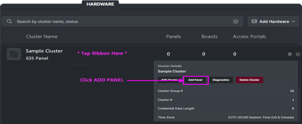
First-time startup: Click on the Sample Cluster ribbon to expand the Cluster Details dropdown.
-
There are no panels, boards, or access portals (doors/readers)
-
The Cluster ID and Cluster Group ID and are already set up.

User Dashboard > Hardware screen: Cluster List (image cropped to exclude dashboard)
-
-
On the Cluster Details dropdown, click the Edit Cluster button to open Cluster Settings Editor.
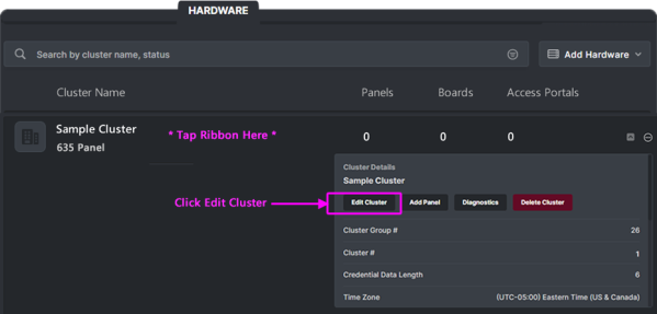
Cluster programming > Cluster Ribbon showing the Cluster Details dropdown expanded
PROGRAMMING CLUSTER NAME & TYPE:
The options in the Cluster Settings Editor apply to all panels in this cluster.
-
(optional) You can Upload Logo/Photo image - as desired.
-
(fixed/static) Notice your Cluster Group ID should already be set to the correct number.
NOTE: This number must be configured into all your hardware panels via Panel Status Page. -
Rename the ‘Sample Cluster’ to a logical name (e.g., Main Building, Front Offices, …)
-
Select the Cluster Type according to which panels will be added to the Cluster.
-
635-only = No 700 panels on the cluster.
-
700-only = No 635 panels on the cluster.
-
Hybrid (635/700 mixed) = Both 635 & 700 panels on the cluster.
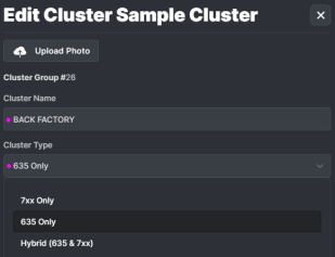
Cluster Settings Editor (cropped for focus)
-
PROGRAMMING CLUSTER SETTINGS: Continued
Continue programming options in the Cluster Settings Editor for all panels in this cluster.
-
(optional) You can enter a Description - as desired.
-
Expand the Advanced Cluster Settings section, and configure the following …
-
Time Zone droplist: configure as needed
-
Credential Data Length droplist: select appropriate value.
-
Unknown Lookup Timeout (seconds): enter value as desired; (default = disabled).
-
Access Rule Override Timeout (seconds): enter value as desired; (default = disabled).
-
Access Portal Type droplist: select the card technology.
-
Lockout After Invalid Attemtps: enter the integer value as desired.
(this is the number of invalid attempts that will lockout the reader )
-
Lockout Duration (seconds): enter value as desired
(this is the duration of the reader lockout)
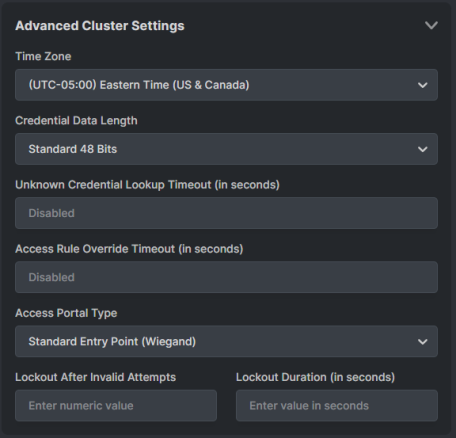
Cluster Settings Editor > Advanced Settings
-
CLUSTER READER LED SETTINGS:
Continue programming options in the Cluster Settings Editor for all readers in this cluster.
-
Expand the Reader LED Options section, and configure the following …
-
(mandatory) LED Behavior When Locked droplist: configure as desired
-
(mandatory) LED Behavior When Unlocked droplist: configure as desired
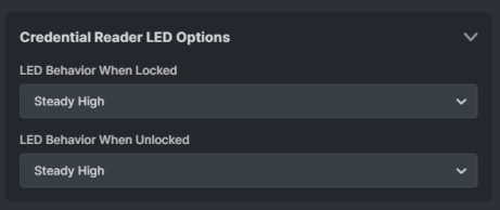
Cluster Settings Editor > Reader LEDs
-
CLUSTER CREDENTIAL SETTINGS:
Continue programming options in the Cluster Settings Editor for all readers in this cluster.
-
Expand the Credentials Config section, and configure the following …
-
ABA Start & Stop Digits: configure as needed; (ABA default= 1 - 60)
-
ABA Fold: configure as needed; (default= ON)
-
ABA Clip: configure as needed; (default= OFF)
-
Wiegand Start & Stop Bits: configure as needed ( 0 – 255 )
-
Cardax Start & Stop Bits: configure as needed ( 34 – 59 )
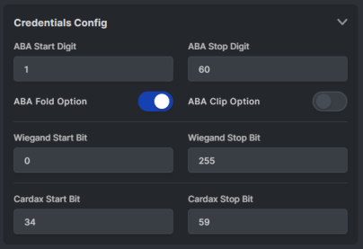
Cluster Settings Editor > Credential Settings
-
SAVING CLUSTER SETTINGS:
User must save Cluster Settings before exiting the Cluster Settings Editor.
-
When programming is finished you must save your changes.
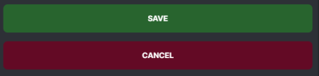
SAVE = Save the Cluster Settings.
CANCEL = Close Editor without saving changes (changes will be dumped.)

-
See next section to Add a Panel.
ADDING A PANEL IN THE POLARIS SYSTEM
You can add Panels, Boards from the Hardware tab.
OPENING THE PANEL SETTINGS EDITOR:
-
Select the Hardware tab from the menu, Click on the Cluster Name to expand the Details.
-
On the Cluster Details dropdown, click the Add Panel button to open Panel Settings Editor.
Panel programming > Cluster Ribbon showing the Cluster Details dropdown expanded
PROGRAMMING PANEL SETTINGS:
-
(mandatory) You must enter a logical Panel Name - as desired.
-
(optional) The Panel Location should contain a brief text that indicates where the Panel is located.
-
(mandatory) User must select the Panel Model: - 600, 635, 708
-
(mandatory) User must enter the Panel Unit Number: - 1, 2, 3, …
(This number must match the programming in the panel.)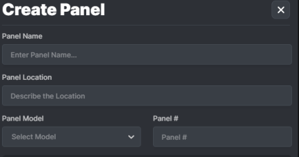
Panel Settings Editor > Configuring a panel.
PANEL SETTINGS – ADDING A DRM BOARD:
When you add DRM Boards, you must choose which section is used, and its purpose (credential reader, access portal, …).
-
Click on the ADD BOARD button to add a board to the panel.
-
Enter the Board ID – this must be the ID number of the actual board
-
Select the Board Type (DRM, etc)
-
Dual Reader Module (DRM 635)
-
-
For the DRM board you must choose the purpose of each Section.
-
Access Portal (Door / Reader)
-
Credential Reader (such as an enrollment reader
-
-
Clicking the ADD BOARD button will add the next board.
-
Clicking the Remove Button will remove the selected board.
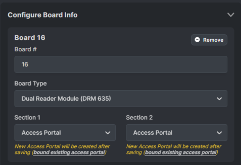
Panel Settings > Adding a board
-
-
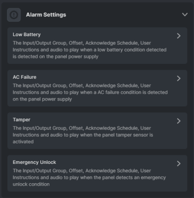
Expand the Panel Alarms and configure their options as appropriate:
-
Low Battery
-
AC Failure
-
Tamper
-
Emergency Unlock
-
-
Click the green CREATE button to create your Panel.
NOTE: The system will automatically create the appropriate peripheral devices in the system for you to configure (doors/readers, inputs, etc)
-
Continue to the next section to Update Flash to the new Panel.
UPDATING FLASH IN A NEW PANEL
You can update the panel flash code from the Panel Details dropdown.
OPENING THE PANEL DIAGNOSTIC COMMAND EDITOR
The Diagnostic Command Editor allows the user to send commands to the selected panel.
-
Click on the Cluster Ribbon to see the List of Panels.
-
Click on your newly added Panel Name to expand the Panel Details.
-
On the Panel Details, clicking the Diagnostic button will open the Diagnostic Command Editor.
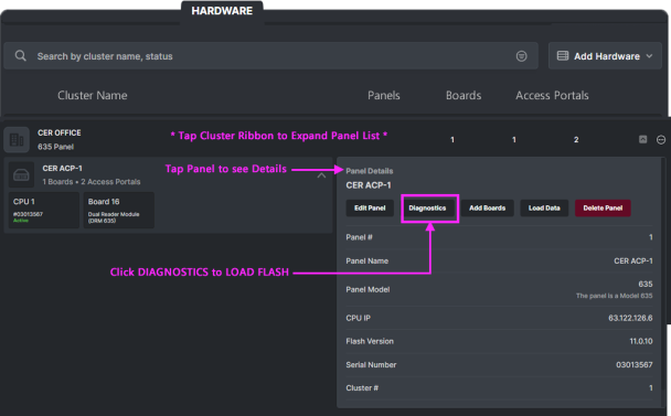
Panel Details > Panel Diagnostic button
-
Continue on next page.
CONFIRM PANEL CONNECTION
Before attempting to load flash, you need to verify that the panel is connected.
IMPORTANT CONNECTION INFO: Panel CPU must have the Cluster Group ID pre-configured in order to connect. If your CPU is below the minimum required flash code (V 11.0.12), you should use TeraTerm/Putty to configure the correct Cluster Group ID so that the panel will connect and the flash can be upgraded. You will find the Cluster Group ID in the Cluster/User Dashboard.
-
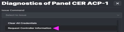
When you click on the Diagnostic button the Diagnostic Command Editor will open.
-
Select “Request Controller Information” from the Command droplist.

-
In the Controller Information results, confirm the following …
-
Panel Status is “Connected”
-
Activity Logging is “Enabled”
-
Panel version number is displayed
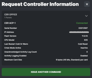
Diagnostic Command Results: Get Controller Information
-
-
Click ISSUE ANOTHER COMMAND button to return to the Command droplist.
-
Continue to the next page to Load Flash
LOADING FLASH TO A PANEL
After confirming that the panel is connected, you can load flash
-
Clicking on the active panel’s Diagnostic button will return user to the Command Editor.
-
Select Flash Loading option from the Command droplist.
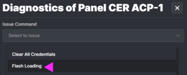
Panel Diagnostic Editor > Flash Loading option
-
Click the Flash Image droplist and choose the current release version for your system.
(minimum required version 11.0.12 or higher – see important version notice on prior page)
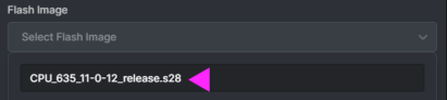
Panel Diagnostic Editor > CPU Flash Image option (versioned)
-
Click the ISSUE COMMAND button. to queue the flash load.

-
Click the BEGING FLASH LOAD button. to start flash load.

-
Continue to next page to see the Flash Loader Processor.
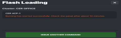
FLASH LOAD PROCESS - Continued ...
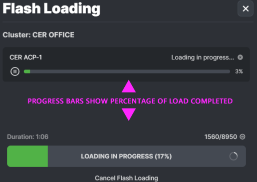
After pressing BEGIN FLASH LOAD (previous step), the Flash Loading will start.
-
The Flash Load Processor shows the percentage of progress for the flash load.
-
Click the BURN ALL button when the Load is finished, to save flash to the CPU permanent memory.

-
When the Flash Loading Processor confirms that Burning Flash has started successfully, user should check the panel in about 10 minutes.
-
Continue to next page to complete the process.
CONFIRM PANEL VERSION UPDATED
User can get controller information to confirm panel updated, from the Panel Diagnostics Editor.
-
Click on ISSUE ANOTHER COMMAND button from the Flash Processer.
-
Select “Request Controller Information” from the Command droplist to verify that the panel has reconnected.
-
In the Controller Information results, confirm the following …
-
Panel Status is “Connected”
-
Activity Logging is “Enabled”
-
Panel version number: SHOULD BE UPDATED TO NEW FLASH VERSION
(if Panel Status is “Disconnected”, wait a few minutes and reissue the request command.)_383x327.png)
Diagnostic Command Results: Get Controller Information
-
-
Continue on next page
UPDATE DAUGHTER BOARDS
User can update the daughter boards from the Panel Diagnostics Editor, after confirming the flash.
-
Click on ISSUE ANOTHER COMMAND button from the Controller Results screen.
-
Select the Update Daughter Boards option from the Panel Diagnostics Editor.
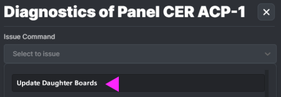
-
Click the ISSUE COMMAND button to begin the updating daughter boards.
-
After the boards have been updated (several minutes), the user can return to the Diagnostics and reissue Request Board Information to ensure the board flash version has updated.
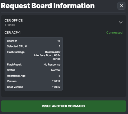
Request Board Information Results
EDITING ACCESS PORTALS IN THE POLARIS SYSTEM
You can edit the Access Portals from the Access Portals tab.
-
Select the Access Portals tab from the menu to start editing Reader/Door properties.
-
Click on the desired Access Portals Ribbon to begin configuring …


-
User can Upload a Photo of the portal as desired.
-
Enter the Access Portal Name as a logical name that makes sense to the system operators of the facility (like Front Lobby or Shipping Door …).
-
Select the Access Portal Type
-
Enter the Location as desired
-
(optional) Enter a Comment as needed.
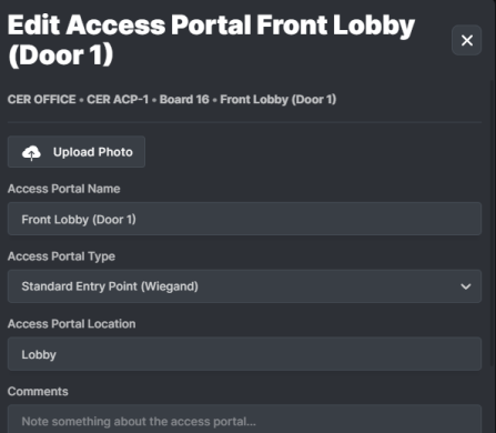
Access Portal Programming
ADDING SCHEDULES TO THE PORTAL:
User can assign schedules to the Portal / Door
-
. Click on the Schedules ribbon to expand the Schedules Settings.
-
Select the Schedules that affect the Reader/Door/Portal including crisis mode as needed.
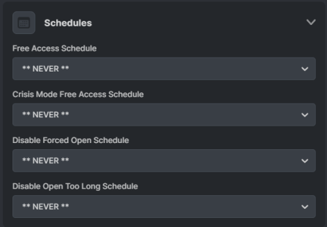
Continue on the next page.
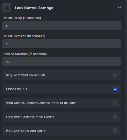
PROGRAMMING LOCK RELAY SETTINGS
User can program the settings to control the Portal / Door Locking.
-
. Click on the Lock Settings ribbon to expand the Lock Settings.
-
Select the Schedules that affect the Reader/Door/Portal including crisis mode as needed.
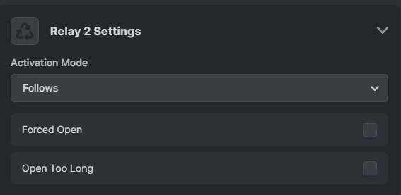
PROGRAMMING RELAY-2 SETTINGS
User can program the settings to control Relay-2.
-
. Click on the Relay-2 Settings ribbon to expand the Relay-2 Settings.
-
Configure the remaining options as needed for the Entry Point.
-
Click the SAVE button to save changes.
RESULT: The Portal List should be updated immediately with name change.
-
Clicking the Discard button will dump all changes.
-
Clicking Cancel will dump all changes.
LOADING DATA TO A PANEL
After programming is done, user can Load Data to an individual panel from the Cluster Ribbon for any panel in this cluster after you select the panel from the Cluster Ribbon. .
-
Click on the Panel Ribbon to expand Panel Details.
-
Click on the LOAD DATA button.
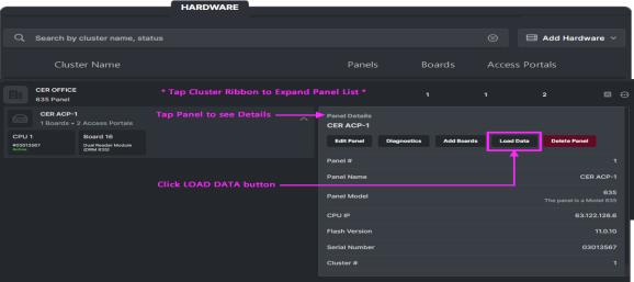
Panel Ribbon with Panel Details expanded
-
Load Data for the panel with all options enabled.
-
Click the green ISSUE COMMAND (i.e., Load Data).
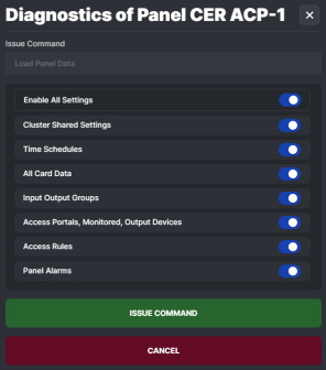
Panel Settings > Load Data screen
ADDING A SYSTEM TEST CARD
You can add Test Cards to the POLARIS System for the purpose of walk-testing your system. The walk-test verifies that your access portals (readers, doors, locks, etc.) are wired correctly and your hardware is operating as expected.
REQUIREMENTS
-
Operator must have the enrollment permissions to be able to enroll cardholders.
-
Test Card must be the correct card type that works with the readers being tested.
STEPS TO ADD A TEST CARD
-
Sign in as an authorized Enrollment Operator (equal or higher permissions).
-
Click the Cardholder tab on the Menu Bar.
-
Click the [Add Cardholder] button.
-
(required) Enter the First and Last Name of the cardholder (i.e., Test Cards).
-
(required) Enter a Primary Email Address.
-
Click the [Add New] Credential button to open the Editor ...
-
Add a logical Card Name (like ‘Valid Test Card 1’, or whatever deemed appropriate)
-
Select the appropriate Card Format (such as ABA or Wiegand).
-
Enter the Card Code, including facility or site code - as needed.
-
Select the Activation Date to make the card active.
-
Make sure the “Active” toggle button is ON (not grayed).
-
Click SAVE button to save the card settings.
-
-
After the Card Settings are saved, make sure the Card Active toggle button is ON (not grayed)
-
Also make sure the Active Cardholder toggle button is ON (not grayed)
-
Click on the Access Permissions to expand the Access Permissions dropdown.
-
Set the Cluster Name of the hardware to be tested.
-
For Valid Access Test Card: set Access Group Slot-1 to the **UNLIMITED ACCESS** option
-
-
Click CREATE button to save the Test Cardholder Record (at the bottom of Cardholder Editor).
-
The system should display a Cardholder Saved message box to confirm the record was saved.
ABOUT WALK-TESTING THE HARDWARE/DOORS
Use Test Cards to verify the hardware’s basic wiring and event communication.
SCOPE OF TEST:
-
The walk-test validates operational behavior of hardware when access should be granted or denied.
-
The walk-test is not verifying custom programming of schedules and access rules (groups/profiles).
PREREQUISITES
-
You must have given access permissions to the Test Cards for the access points you need to test.
-
The hardware must be fully installed and configured and must be connected with the event server.
VALID ACCESS TEST STEPS
-
Present the Valid Access Test Card to the reader and verify the behavior and operation of the reader and door hardware is correct ...
-
Reader works as expected and detects the access card you present.
-
-
Reader beeps as expected (based on default programming)
-
Reader LED blinks and change states as expected (based on access granted)
-
Door unlocks/opens as expected (based on unlimited /always access permissions)
-
Door relocks and reader returns to idle when the door contact closes (based on door/lock timers)
-
Door relocks and reader returns to idle state after door is held open until reclose timer elapses
-
Verify the hardware events are communicated the Event Server.
-
The Valid Test Card should get an “access granted” event in the Event Screen.
-
Also, door status events should be displayed for the access point as appropriate - based on the actions of the person walk-testing the system – for example: a door open too long event is reported if the door is held open until the reclose timer elapses. Followed by a door closed event after the system senses door contacts are closed. This verifies that the door contact positions are being detected/reported correctly.
-