OSDP Readers & Adapter Board Install
This topic covers the OSDP Adapter Board Install onto the 635-DRM Board, as well as OSDP Readers Configuration and Wiring.

TOPIC FEATURES
OSDP ADAPTER BOARD FUNCTIONALITY OVERVIEW
OSDP ADAPTER BOARD COMPONENT-LAYOUT
OSDP ADAPTER BOARD INSTALLATION
FARPOINTE OSDP READER (CSR-6.2L/6.4L Rev2)
OSDP ADAPTER BOARD FUNCTIONALITY OVERVIEW
The 700 OSDP Adapter Board is compatible with the 635 DRM (Dual Reader Module).
-
When a 700 OSDP Adapter Board is attached to the DRM Board, then both sections are designated for OSDP Readers.
-
If you have NON-OSDP Readers, they must be connected to a separate DRM Board.
700 OSDP Adapter Board Compatibility and Functionality
-
700 OSDP Adapter Board is pre-flashed from the factory (ready to install; no addressing needed).
-
700 OSDP Adapter Board supports 2 OSDP Readers when attached to a 635-DRM board.
-
700 OSDP Adapter Board is compatible with the 635-DRM Board.
-
OSDP Reader data is converted to Wiegand data.
-
System Galaxy Reader Properties: set the Reader Type to Wiegand.
-
System Galaxy Reader Properties: set the LED Line as needed (see table below).
Reader Property
DRM LED LINE
Reader Behavior
OSDP COMMAND
Color Value Set
Steady Low
Green (solid)
value = 2
Steady High
Red (solid)
value = 1
Strobe
Green / Black (off)
(blinking)
value = 2+0
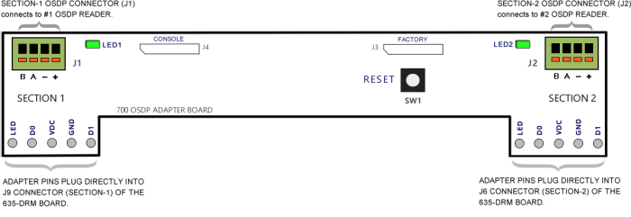
700 OSDP ADAPTER BOARD – COMPONENT LAYOUT
This section provides a list of the important board components.
BOARD COMPONENTS
SW1 – Reset Switch
J1 – RS-485 / OSDP Reader Connector (4-pin; RS-485 2-wire protocol) for Section-1 reader port.
J2 – RS-485 / OSDP Reader Connector (4-pin; RS-485 2-wire protocol) for Section-2 reader port.
J3/J4 – Factory and Console programming ports, respectively (factory use only).
J5/J6 – 5-Pin Reader Connector header pins: for connecting/mounting Adapter Board to the DRM Reader ports.
LED1 Green – Indicator for Section-1/Reader-1
LED2 Green – Indicator for Section-2/Reader-2
LED STATES:
Fast Blink = communication is occurring
Slow Blink = no communication, (Adapter Board is Powered ON)
FIGURE 1 : 700-Series OSDP Adapter Board - Component Layout
INSTALLING 700 OSDP ADAPTER BOARD
The 700 OSDP Adapter Board must be attached to a 635-DRM (Dual Reader Module) at the 5-pin connector pins on the adapter board. Then the OSDP Reader can be wired to the Adapter board. The Galaxy Controller will convert the OSDP Reader data to Wiegand data.
REQUIREMENTS
-
The 635 Controller must already be installed and flashed/programmed, up and running and connected to System Galaxy Event Server.
-
The 635-DRM Board must already be installed, addressed, flashed and actively communicating. You should be able to see the DRM Board in the System Galaxy Controller Programming screen.
-
In the System Galaxy Reader Properties screen, the Reader Type must be configured as Wiegand.
-
In SG Reader Properties screen, LED Behavior can be set as desired - i.e. low (solid green), high(solid red) , strobe (blinking green).
NEW INSTALL STEPS
-
Install the 635-DRM Board into the Controller Cabinet if it is not already installed.
-
Remove both orange Reader connectors from the 635-DRM Board (J9 and J6).
-
Loosen the contact screws for the positions labeled LED, D0, VDC, GND, and D1.
-
Attach both orange connectors onto the 5-pins of the 700-OSDP Adapter Board.
-
Make sure you correctly align the contact positions – LED to LED; D0 to D0; VDC to VDC; GND to GND; D1 to D1.
-
IMPORTANT: Make sure the 5 Pins are fully seated on the orange connectors of the DRM Board.
-
-
Tighten all 5 contact screws for LED, D0, VDC, GND, and D1 on both reader connectors.
-
Once the 700 Adapter is correctly attached to the orange reader connectors, then you can plug the orange connectors into the DRM Board.
RESULT: This attaches the 700 Adapter Board to the DRM Board.
-
Adapter Board Section-1 should be plugged into Section-1 of the DRM Board (J9)
-
Adapter Board Section-2 should be plugged into Section-2 of the DRM Board (J6)
IMPORTANT: Make sure the Adapter Board pins are securely attached to the orange connectors.
And make sure the orange connectors are fully seated in the DRM Board.
-
Figure 2 –700 OSDP Adapter Board as viewed when attached to the 635-DRM Board’s orange connectors (edge view)
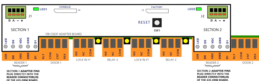
Diagram of 700 OSDP Adapter Board attached to Orange Connectors of the 635 DRM Board
CONFIGURING THE OSDP HID SIGNO READER
Configuring the HID SIGNO OSDP Reader is done using the HID Reader Manager app.
REQUIREMENTS:
-
You must download the HID Reader Manager App (Mobile App) from Apple Store or Google Play.
-
Create your user login credentials, as required.
-
It is recommended that you pre-configure the HID OSPD Reader before you install it.
STEPS:
-
Launch the HID Reader Manager App and sign in as required.
-
Choose the [Scan for Readers] option.
RESULT: A list of mobile-enabled/mobile-ready readers will appear on the app screen. -
Select the correct reader from the reader list.
-
Choose the [Inspect] option.
-
Choose the [Detailed Config] option.
NOTE: The mobile app may prompt you to power cycle your OSDP Reader. Follow the instructions displayed on the mobile app.
-
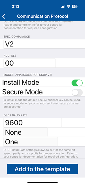
Configure Reader type/protocol as follows ...
-
Select [Communication Protocol] option
-
Enable (turn on) the OSDP option
-
Set Compliance to “V2”
-
Set the Address = “00”
-
Set the Mode to “Install”
(unencrypted) -
Set Baud Rate to “9600”
Parity = None
Stop Bit = One -
Tap the [Add to Template] button
-
Tap the BACK ARROW button
-
Tap [ Apply Selected Items ] button
-
CONFIGURING INVIXIUM OSDP READER
Configuring the Invixium OSDP Reader is done by downloading the IXM Web Application.
Requirements
-
Reader Power Supply Ground can be bonded to Controller Power Supply Ground
-
If using Poe for Power check with Reader manufacture documentation.
Invixium Reader Wiring
Using the bottom connector on the Invixium Reader, and land reader wiring to the OSDP Adapter as shown in table below…
|
Invixium (Bottom Connector) |
OSDP Adapter Board |
|---|---|
|
Red (+12VDC ) |
use a separate power supply |
|
Black (- Ground ) |
use a separate power supply |
|
Blue RS485 + |
A (J1 or J2) |
|
Blue/Black RS485 - |
B (J1 or J2) |
Configure Communication and LED Settings
-
Select the OSDP option on the Access Control tab of Invixium Devices page.
-
Comm Settings: Baud Rate9600; Parity None; Stop Bit1; Timeout 3000 msec.
-
Security Key Type: AES128
-
Configure OSDP Events as follows …
|
EVENTS |
ON COLOR |
OFF COLOR |
ON TIME |
OFF TIME |
DISPLAY |
|---|---|---|---|---|---|
|
Access Granted |
RED |
RED |
100 msec |
100 msec |
Y |
|
Access Denied |
GREEN |
GREEN |
100 msec |
100 msec |
Y |
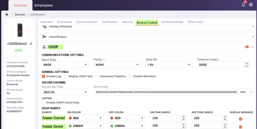
Invixium Software: Device Page/Access Control Settings
Galaxy Recommendation for LED Settings for Invixium
The Door Lock state (lock/unlock) drives the LED behavior, which is configurable in the Galaxy Cluster Properties screen, LED Options tab.
-
The LED Settings apply to all readers on the same Cluster.
-
When the Door Lock changes state, the Reader LED will follow the assigned behavior.
NOTICE: Be aware that the ‘Strobe’ setting will cause the Invixium reader to activate its piezoelectric buzzer. And the reader will continue resounding the piezoelectric buzzer until the lock state changes.
-
From the SG Menu: Configure > Hardware > Loops/Clusters
-
Click the Edit button and pick the Cluster Name that the Invixium Readers belong to
-
On the LED Options tab set the LED Behaviors using table below …
-
Click the Apply button to save LED Settings.
|
“When Door is Locked” |
“When Door is Unlocked” |
|---|---|
|
Steady Low |
Steady High (recommended) |
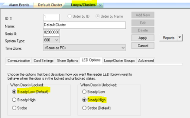
System Galaxy: Cluster Properties / LED Settings
CONFIGURING WAVELYNX ETHOS READER
The Wavelynx ETHOS Reader should come factory defaulted to the “OSDP Auto-Detect mode”, which means the reader can detect and negotiate the OSDP connection when it is first powers up and connects (in its initial start-up sequence).
TERMS
|
TERMINOLOGY |
DEFINITION |
|---|---|
|
AV Behavior |
AV Behavior refers to the ‘audio/visual signals’ that happen during start-up or operation – basically it is |
|
Standard Behavior |
Standard Behavior means the ‘operating behavior’ (a) at startup sequence (beeps & LED blinks signal configuration/capabilities ); and (b) response to access credential scans (beeps & LED response). |
|
Startup sequence |
Startup Sequence refers to the AV Behavior (pattern of beeps & blinks) when the reader is powered on. NOTICE: the startup sequence at the initial startup is different than the startup sequence at a normal startup. When you are installing, you need to pay attention to the startup sequence beeps/blinks when the reader powers-up – because this signals which operating mode the reader is set for. |
|
Initial Startup
|
Initial Startup (first-time power-up) occurs when power is applied to the reader for the first time. During initial startup the reader will display a specific sequence of Beeps and LED blinks that signal the compatible card technologies and signals the default operating mode/or auto-detect mode. |
|
Normal Startup |
Normal Startup is any power-up that occurs after the initial startup negotiation has happened. |
REQUIREMENTS
-
Ethos Readers should be in OSDP Auto-detect Mode so that they auto-negotiate the OSDP Connection (factory default).
-
Ethos Keypad Reader should be configured for 8-bit burst (factory default).
INITIAL STARTUP SEQUENCE (Confirming the Reader is in Auto-Detect Mode)
BEST PRACTICE: You should confirm that the reader is in OSDP Auto-Detect Mode BEFORE you connect data lines.
This is done by powering-up the reader to observe the initial startup sequence and determine which mode the reader is configured for.
-
If the reader is not in auto-detect mode, then it might not be able to read OSDP credentials after the data lines are connected.
The reader will need to be re-flashed using the Wavelynx Configure App. -
If the reader is not in the auto-detect mode, it may not function properly when connected to the hardware panel.
STEPS
-
(on test bench) First do not connect data lines. Only connect power wires. (Red = +12vdc; Black =ground).
-
Power-up the ETHOS Reader and observe Reader Behavior during its initial startup sequence.
EXPECTED RESULT: The Reader LED Behavior will beep/blink to signal which (A) Supported Technologies and (B) Qutput Mode.
(A) Supported Technologies: The reader should make 1 Beep/1 Blink for each color listed (if purchased from Galaxy) ...
-
BLUE í = 4.0 Hardware Only
-
RED í = Mobile
-
GREEN í = 13.56 MHz Smart Cards (HF)
-
AMBER í = 125 kHz Prox (LF)
(B) Output Mode: The reader should signal Auto-Detect Mode (if purchased from Galaxy) ...
-
1 BEEP/1 RED í = Wiegand Only (reader will need to be re-flashed)
-
2 BEEPS/2 GREEN íí = OSDP Only (reader needs re-flashing if card code cannot be read)
-
4 BEEPS/4 GREEN íííí = OSDP AUTO-DETECT MODE << you want to see this mode.
-
-
If the ETHOS Reader is not in Auto-Detect Mode, you can re-flash it using Configure by Wavelynx. Download “Configure by Wavelynx” from Apple Store (iPhone) or Google Play (Android).
-
If the reader is in OSDP Auto-Detect Mode, you can connect data lines to the OSDP Adapter Board.
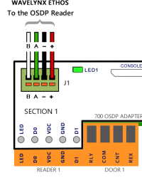
Wavelynx ETHOS OSDP
-
VDC - Red
-
GND - Black
-
A - Green
-
B - White
-
-
The ETHOS Reader will auto-negotiate the OSDP handshake.
RESULT: the reader should read the test card and get either a Valid Access or Not In System. -
Reset the power on the ETHOS Reader to confirm the output mode.
RESULT: the Reader startup sequence should indicate …-
2 BEEPS/2 GREEN íí = OSDP Only (re-flashing only needed if card code cannot be read)
-
-
Now, the ETHOS Reader should operate correctly (read Credentials) and will permanently stay in OSDP Mode.
-
NOTICE: IF the reader does not read cards correctly or if it indicates the wrong output mode, it must be re-flashed.
-
First download the mobile app: “Configure by Wavelynx” from Apple Store / Google Play.
-
Then contact authorized tech support for the correct key code after you have the App installed.
-
Use the Configure App to re-configure the reader to the correct flash-setup and put the reader in the correct output mode.
-
-
If you have a Wavelynx KEYPAD READER: the keypad must be configuration for 8-bit Burst (factory default from Galaxy).
-
KEYPAD OPERATION: keypad will accept up to 5 digits (not to exceed 65535).
-
Pressing # will send PIN data.
To Configure the Keypad Mode for 8-bit Burst, do the following ...
-
Power-up the reader (it should beep/blink twice to indicate OSDP Mode)
-
within 1 minute of power-up, enter *88889999 (the keypad config code)
RESULT: the reader will signal 3 BEEPS/3 GREEN LED FLASHES ííí
-
enter *8 (for 8-bit burst) within 2 seconds of entering the keypad code in Step b.
RESULT: the reader will signal 3 BEEPS/3 GREEN LED FLASHES ííí (mode is set)
-
RELATED MATERIALS:
-
Wavelynx Ethos Reader Guide explains the AV Behaviors (beeps/blinks and colors) :
https://support.wavelynx.com/en_US/how-tos/technical-guide-on-ethos-readers -
To download the Configure App: search for ”Configure by Wavelynx” (Apple Store/Google Play)
-
Printable instructions for setting up the Configure App is on > Configure Experience page :
-
Additional Configure App product info wepage: https://wavelynx.com/products/configure
CONFIGURING A FARPOINTE OSDP READER (csr 6.2/6.4)
Galaxy supports Farpointe OSDP CSR 6.2L and CSR 6.4L models, which include a keypad.
Go to the following section for the complete wiring and install information for this Farpointe ODSP Reader.
The reader should work from the factory defaults …
|
Farpointe CSR-6.2L/6.4L Rev2 |
|---|
|
VDC - Red |
|
GND - Black |
|
A - Green |
|
B - White
|
|
|

WIRING OSDP READERS TO 700-ADAPTER BOARD
The OSDP Readers must be connected to the RS485 Connectors at J1 and J2 on the 700-OSDP ADAPTER BOARD.
REQUIREMENTS:
-
It is recommended that you pre-check and pre-configure (if needed) your OSPD Readers before you install them.
See the previous section for configuration instructions for your brand of reader.
STEPS:
-
Connect your OSDP Reader to the 700-Adapter Board at the RS485 Connector (J1 or J2).
NOTE: Use the correct pinout shown for your brand reader on the table below.
|
J1 Contacts |
HID SIGNO |
Wavelynx ETHOS |
Farpointe CSR-6.2L Rev2 |
|---|---|---|---|
|
12vdc |
VDC - Red |
VDC - Red |
VDC - Red |
|
Ground |
GND - Black |
GND - Black |
GND - Black |
|
A |
A - White |
A - Green |
A - Green |
|
B |
B - Green |
B - White |
B - White |
|
|
|
|
|
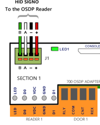
Diagram (above) shows OSDP Reader wiring pinout of the OSDP Adapter Board, RS485 Connector (J1/Section1). The Section-1 contact pins of the Adapter Board are plugged into the Reader-1 Orange Connector on 635-DRM.
-
On the 700 Adapter Board, the Green LED should be blinking when the reader is connected and has been correctly programmed. The Green LED is located beside the RS485 Connector (J1 or J2).
NOTE: If the LED is slow blinking, the board has power, but RS-485 communication is not happening. -
You can present a Valid Test Card to the OSDP Reader to verify that the board is reading the card, and that the event logs to the Event Screen, and that the door unlocks, as appropriate.
Notice: The door will unlock based on access privileges assigned to the test card during enrollment.