635-FTS Board Flashing Procedure (via 600/635 Factory Port)

This procedure describes how to load flash code to a 600- or 635-series boards using a 635-FTS Board and FTS ribbon cable (via Factory Port).
MATERIALS AND REQUIREMENTS
|
Materials 6 |
|
Requirements 6 |
|
|
|
|
|
|
|
|
|
|
|
|
|
|
|
|
|
|
PART 1 - CONNECT AND POWER-UP 635-CPU AND TARGET BOARDS
-
Power up the 635-model FTS-CPU using a 12 VDC power source.
-
Connect 635 FTS-CPU to a Laptop/PC using the Cat5e cable.
-
Open the native Panel Status page by typing the CPU’s IP Address into a Browser (default factory IP = 192.168.0.150).
-
Locate the serial number on a label on the Target Board (you will need to know this exact number for a later step).
-
Power up the Target Board using a 12 VDC power source.
-
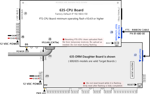
Connect the Factory FTS Cable to the FTS-CPU ‘Factory Test’ port and to the Target Board ‘Factory’ port.
PART 2 - DISABLE ALL EVENT SERVERS (VIA THE PANEL WEB PAGE)
-
Click the Panel Configuration page and uncheck all Event Servers (1 - 4).
-
Click the Update button to save settings.
PART 3 - CONFIRM THE EMBEDDED FLASH FILE VERSION
New 635-CPU Boards are all shipped with the ‘current factory operating flash’, and the native (in-built) Factory Test Station, and the embedded Flash.
-
Click the Factory Function page and verify if the Embedded Column’s flash version matches your Target Flash Version …
-
IF the Embedded Column does not match your Target Flash Version, go to PART 4 – UPLOAD A TARGET FLASH FILE .
-
IF the Embedded Column matches your desired Target Flash Version, go to PART 5 - FLASH A TARGET BOARD.
-
PART 4 – UPLOAD A TARGET FLASH FILE
-
Go to the Factory Function page to begin.
-
Click the Browse button and find the correct Target Flash file by navigating to the appropriate folder path (shown below). You must choose the correct model number and board type of your target board (600 or 635).
-
USB path X:\\Auxiliary\System Galaxy\FTS635\Factory Testing\S28\ your_model\ your_board-type\ Previous Version …\
-
PC path C:\\GCS\System Galaxy\FTS635\Factory Testing\S28\ your_model\ your_board-type\ Previous Version …\
-
-
Select the correct Flash File that matches your Target Flash Version and click the Open button.
-
Click the [Upload] button to load the Flash File to the FTS-CPU memory bank.
( Real-time upload status will display in the Activity Log section of the web page. ) -
Click OK button when the upload is completed. Your Target Flash Version will display in the Uploaded Column.
|
M |
DO NOT RESET THE FTS-CPU BOARD! A reset will delete the target flash file. Reload target flash If needed. |
PART 5 - FLASH A TARGET BOARD
-
Click the Flash Version link that is shown beside the board type you want to flash (i.e. 600 or 635 DRM/DPI, DIO, DSI, etc.).
-
When prompted, enter the Target Board converted serial number. See examples in Conversion Chart below:
-
The Serial Number must be exactly 8 digits when it is entered into the FTS prompt.
-
You must enter the converted serial number with the format used by the FTS. You must swap a zero from the 2nd or 3rd position and place it in the leading position. The serial number label is affixed to the back of the board.
Table 1 Serial Number Conversion Chart:
-
|
MODEL |
6IF BOARD LABEL SAYS THIS |
6 YOU WILL ENTER THE CONVERTED SERIAL NUMBER AT THE FTS |
|
|
600 CPU 4 |
No conversion needed |
“0201 …” |
Enter serial number exactly as seen on the board label. |
|
635 CPU 4 |
No conversion needed |
“0301 …” |
Enter serial number exactly as seen on the board label. |
|
600 DPI 4 |
“20012…” converts to |
“02012 …” |
ß the zero was swapped from 2nd pos. to 1st pos. |
|
635 DRM 4 |
“30012…” converts to |
“03012 …” |
ß the zero was swapped from 2nd pos. to 1st pos. |
|
600 DIO 4 |
“23001…” converts to |
“02301 …” |
ß the zero was swapped from 3rd pos. to 1st pos. |
|
600 DSI 4 |
“33001…” converts to |
“03301 …” |
ß the zero was swapped from 3rd pos. to 1st pos. |
|
635 DSI 4 |
“34001…” converts to |
“03401 …” |
ß the zero was swapped from 3rd pos. to 1st pos. |
|
M |
DO NOT DUPLICATE SERIAL NUMBERS! Boards will not function with duplicate Serial Numbers or duplicate Board_IDs. |
-
Click the OK button to begin transferring flash to your target board.
The Activity Log displays progress indicators that show the board flash progress and flash verification progress.
(1) verify the FTS Ribbon Cable is securely attached to the FTS-CPU Factory Test port and the target board Factory port. (2) verify you have uploaded the correct S28 Flash file Flash Version Link for your target board’s model and board-type. The Factory Test Station will not transfer flash if the selected Flash Version Link is for a different board than the target board that is connected.
-
When the Activity Log displays the message “flashing is successful”, you will click the OK button.
-
Press the Reset button (SW1) on the Target Board only, to initialize the target board.
Do not reset the FTS-CPU or you will have to reload your target flash file (that was loaded in Part 4). -
Disconnect the Factory Test Cable from the finished Target Board.
See the System Installation QRS or 635 Hardware Installation Guide for instructions on installing the board, as needed. -
Connect the Factory FTS Cable to the NEXT Target Board at the ‘Factory Test’ port and repeat steps in this section.
-
IF your next target board is the same model and type, you can continue flashing with the currently loaded flash. Repeat the steps in this PART 5 - FLASH A TARGET BOARD.
-
IF your next Target Board is a different model (600 vs 635) or a different board type (DSI vs DIO vs DPI/DRM), then you must upload the correct target file for this board and model (see PART 4 – UPLOAD A TARGET FLASH FILE ).
-