Galaxy Reader Wiring QRG 
1.0 Wiegand Reader - Cable Specs & Wiring
-
5-conductor, 22 AWG, overall shielded; max cable distance is 500 feet.
-
Reader will require separate power supply if the current draw is over 150 mA.
-
Ground the Drain-wire at one end only - at the DRM Board (GND).
-
Refer to reader manufacturer’s instructions for wiring (manufacturer's specs may supersede Galaxy specs).
|
635-DRM Terminal Functions (PN 20-0235-10) |
Wiegand Reader |
|
|---|---|---|
|
LED |
(LED control line) |
LED Control |
|
D 1 |
(Data 1) |
DATA 1 |
|
VDC |
(+12 VDC) ( for +5 VDC use Regulator PN 92-3001-05 ) |
VDC |
|
GND |
(Power Supply Ground) |
GND |
|
D 0 |
(Data 0) |
DATA 0 |
2.0 ABA Reader - Cable Specs & Wiring
-
5-conductor, 22 AWG, overall shielded; max cable distance is 500 feet.
-
Reader will require separate power supply if the current draw is over 150 mA.
-
Ground the Drain-wire at one end only - at the DRM Board (GND).
-
Refer to reader manufacturer’s instructions for wiring (manufacturer's specs may supersede Galaxy specs).
|
635-DRM Terminal Functions (PN 20-0235-10) |
ABA Reader |
|
|---|---|---|
|
LED |
(LED control line) |
LED Control |
|
D 1 |
(Data 1) |
DATA 1 |
|
VDC |
(+12 VDC) ( for +5 VDC use Regulator PN 92-3001-05 ) |
VDC |
|
GND |
(Power Supply Ground) |
GND |
|
D 0 |
(Data 0) |
CLOCK |
3.0 Biometric Reader - Cable Specs & Wiring
-
5-conductor, 22 AWG, overall shielded; max cable distance is 500 feet.
-
Cat-5e Ethernet cable for TCP/IP communication back to the server; max cable distance 300 feet.
-
Reader will require separate power supply if the current draw is over 150 mA.
-
Ground the Drain-wire at one end only - at the DRM Board (GND).
-
Refer to reader manufacturer’s instructions for wiring (manufacturer's specs may supersede Galaxy specs)
-
See next section for information on IDEMIA Morpho Sigma Readers.
|
635-DRM Terminal Functions (PN 20-0235-10) |
Wiegand Reader |
|
|---|---|---|
|
LED |
(LED control line) |
LED Control |
|
D 1 |
(Data 1) |
DATA 1 |
|
VDC |
(+12 VDC) ( Do not use for reader power!) |
VDC |
|
GND |
(Power Supply Ground) |
GND |
|
D 0 |
(Data 0) |
DATA 0 |
4.0 BridgePoint Reader (NON-FICAM)
-
5-conductor, 22 AWG, overall shielded; max cable distance is 500 feet.
-
2-conductor- twisted pair, 22 AWG max cable distance 500 feet (for Mode/Factor Control)
-
Reader will require separate power supply if the current draw is over 150 mA. You must common reader P.S. ground to controller ground.
-
Ground the Drain-wire at one end only - at the DRM Board (GND).
-
Refer to reader manufacturer’s instructions for wiring (manufacturer's specs may supersede Galaxy specs).
-
Min. Board Requirement: 635-DRM Board (Dual Reader Module) – PN 20-0235-10
-
DRM Relay-2 must be use for Mode/Factor Control
MODES/FACTORS:
-
Mode 1 Card Only (high)
-
Mode 2 Card + Pin (low)
NOTES:
-
Mode signal line High (unconnected) for 1-Factor Card Only.
-
Mode signal line Low (connected to ground) for 2-Factor Card + Pin.
-
Place a schedule on Relay-2 in System Galaxy Reader Properties - to alternate Mode/Factor.
|
635-DRM Terminal Functions (PN 20-0235-10) |
Wiegand Reader |
|
|---|---|---|
|
LED |
(LED control line) |
LED1 |
|
D 1 |
(Data 1) |
WEG 1 |
|
VDC |
(+12 VDC) ( Do not use for reader power!) |
VDC (to separate power supply) |
|
GND |
(Power Supply Ground) |
GND (common to controller ground) |
|
D 0 |
(Data 0) |
WEG 0 |
|
635-DRM RELAY-2 |
BridgePoint Mode/Factor |
|
|---|---|---|
|
COM |
(must tie to reader’s power supply ground) |
- - - |
|
NO |
(to mode control line) |
LED 2 |
5.0 IDEMIA (Morpho) SIGMA Biometric Reader - Cable Specs & Wiring
-
3-conductor, 20 - 24 AWG, overall shielded; non-stranded; max cable distance is 500 feet.
-
2-conductor, 16 AWG for at +12vdc (18 AWG for +24vdc) for 500 feet distance. Reader draws 1A at 12v (0.5A at 24v).
-
Cat-5e Ethernet cable for TCP/IP communication back to the server; max cable distance 300 feet.
-
Separate power supply required (current draw is 1A). You must common the reader's power supply ground to controller ground.
-
Ground the drain-wire at one end only - land drain wire at the DRM Board (GND).
-
Refer to reader manufacturer’s instructions for wiring (manufacturer's specs may supersede Galaxy specs).
-
635-DRM Board (Dual Reader Module) – PN 20-0235-10
-
DRM Relay-2 is used to control Sigma “Wait for Panel Decision” for Voice/Prompt synchronization.
NOTES:
-
“Wait for Panel Decision”: Connect Sigma LED1 to the ‘NO’ leg of Relay-2. Tie the ‘COM’ leg of Relay-2 to DRM GND.
-
Set Relay-2 for Timed Mode (1 to 2 secs) and “Valid Unlock” checkbox must be "checked" in Reader Properties screen in the System Galaxy software.
|
635-DRM Terminal Functions (PN 20-0235-10) |
Wiegand Reader |
|
|---|---|---|
|
LED |
(LED control line) |
|
|
D 1 |
(Data 1) |
WIEG DATA 1 |
|
VDC |
(+12 VDC) ( Do not use for reader power!) |
VDC (to separate power supply) |
|
GND |
(Power Supply Ground) |
GND (common to controller ground) |
|
D 0 |
(Data 0) |
WIEG DATA 0 |
|
635-DRM RELAY-2 |
SIGMA “Wait for Panel Decision” |
|
|---|---|---|
|
COM |
(must tie to reader’s power supply ground) |
- - - |
|
NO |
(for voice/prompt control line) |
LED 1 |
6.0 Invixium (IXM) Biometric Reader - Cable Specs & Wiring
-
3-conductor, 22 AWG, overall shielded; non-stranded; max cable distance is 500 feet.
-
2-conductor, 18 AWG for at +12vdc for 500 feet distance. Reader draws 1A at 12v .
-
Cat-5e Ethernet cable for TCP/IP communication back to the server; max cable distance 300 feet.
-
Separate power supply required (current draw is 1A). Must common reader's p.s. ground to controller ground.
-
Ground the drain-wire at one end only - land drain wire at the DRM Board (GND).
-
Refer to reader manufacturer’s instructions for wiring (manufacturer's specs may supersede Galaxy specs).
-
635-DRM Board (Dual Reader Module) – PN 20-0235-10
-
635-DRM LED is used to control reader’s for Voice Command when configured for “Wait for Panel Decision”.
NOTES:
-
The IXM Reader must be configured to “follow panel decision” in the IXM-WEB software in reader configuration screen.
-
Galaxy controller must be set for Door Lock = Steady-High; Door Unlock = Steady-Low in the LED Options tab of the Loop/Cluster Properties screen.
|
635-DRM Terminal Functions (PN 20-0235-10) |
Invixium Reader |
|
|---|---|---|
|
LED |
(LED control line) |
ACP LED1 (control Voice Command) |
|
D 1 |
(Data 1) |
WIEG DATA 1 |
|
VDC |
(+12 VDC) ( Do not use for reader power!) |
|
|
GND |
(Power Supply Ground) |
VIN GND (bond to controller ground) |
|
D 0 |
(Data 0) |
W DATA Out 0 |
|
VIN + (VDC) to separate power supply |
||
|
VIN – (GND) to separate power supply |
||
7.0 SCM Reader (NON-FICAM)
-
5-conductor, 22 AWG, overall shielded max cable distance 500 feet.
-
2-conductor- twisted pair, 22 AWG, max cable distance 500 feet (for Mode/Factor Control).
-
Reader will require separate power supply if the current draw is over 150 mA.
-
You must common reader P.S. ground to controller ground.
-
Ground the Drain-wire at one end only (at the DRM Board “GND”).
-
Refer to reader manufacturer’s instructions for wiring (manufacturer's specs may supersede Galaxy specs)
-
Min. Board Requirement: 635-DRM Board (Dual Reader Module) – PN 20-0235-10
-
DRM Relay-2 must be use for Mode/Factor Control.
MODES/FACTORS
-
Mode 1 Card Only
-
Mode 2 Card + Pin
NOTES:
-
Mode signal line = High (unconnected) for 2-Factor Card + Pin.
-
Mode signal line = Low (connected to ground) for 1-Factor Card Only, the
-
Place a schedule on Relay-2 in System Galaxy Reader Properties to alternate Mode/Factor.
|
635-DRM Terminal Functions (PN 20-0235-10) |
SCM Reader |
|
|---|---|---|
|
LED |
(LED control line) |
LED Control |
|
D 1 |
(Data 1) |
D 1 |
|
VDC |
(+12 VDC) ( Do not use for reader power!) |
VDC (to separate power supply) |
|
GND |
(Power Supply Ground) |
GND (common to controller ground) |
|
D 0 |
(Data 0) |
D 0 |
|
635-DRM RELAY-2 |
SCM Mode/Factor |
|
|---|---|---|
|
COM |
(must tie to reader’s power supply ground) |
REL 2 |
|
NO |
(to mode control line) |
RELGRN |
8.0 STid Easyline Reader
-
5-conductor, 22 AWG, overall shielded max cable distance 500 feet.
-
2-conductor- twisted pair, 22 AWG, max cable distance 500 feet.
-
Reader will require separate power supply if the current draw is over 150 mA
-
You must common reader P.S. ground to controller ground.
-
Ground the Drain-wire at one end only (at the DRM Board “GND”).
-
Min. Board Requirement: 635-DRM Board (Dual Reader Module) – PN 20-0235-10
-
Refer to the reader manufacturer’s instructions for wiring (manufacturer's specs may supersede Galaxy specs).
IMPORTANT NOTICES
-
Easyline PC2 Readers are configured to only read STid PC2 encoded smart cards.
No other smart cards can be read by this reader. -
The STid Reader with Proximity Module (acts as pass-through data) can read 125KHz cards (EM/ HID PROX/ AWID/ IOPROX/ INDALA), in addition to the 13.56 MHz STid PC2 Smart Cards.
-
Do not mix non-mobile STid Readers with mobile-enabled (Blue) STid Readers in the same system.
-
The mobile-enabled (Blue) STid Readers can only use the free Green Mobile ID (Mobile app).
-
Before power is applied, you must connect all accessory and field wiring, and firmly mount the reader to the wall.
-
The tamper switch is an accelerometer and is calibrated upon power up. If the reader is moved after being powered up, the reader will be in a ‘tamper’ state and will not send the correct 26 -bit Wiegand data but will send 30-bit data to indicate tamper state.
|
635-DRM Terminal Functions (PN 20-0235-10) |
STid Easyline Reader |
|
|---|---|---|
|
LED |
(LED control line) |
LED Control |
|
D 1 |
(Data 1) |
D 1 |
|
VDC |
(+12 VDC) |
VDC |
|
GND |
(common Reader’s p.s. ground to Controller ground) |
GND (common to controller ground) |
|
D 0 |
(Data 0) |
D 0 |
9.0 STid Reader with Galaxy Configuration
-
5-conductor, 22 AWG, overall shielded max cable distance 500 feet.
-
2-conductor- twisted pair, 22 AWG, max cable distance 500 feet.
-
Reader will require separate power supply if the current draw is over 150 mA.
-
You must common reader P.S. ground to controller ground.
-
Ground the Drain-wire at one end only (at the DRM Board “GND”).
-
Min. Board Requirement: 635-DRM Board (Dual Reader Module) – PN 20-0235-10
-
Refer to the reader manufacturer’s instructions for wiring (manufacturer's specs may supersede Galaxy specs).
IMPORTANT NOTICES:
-
STid Readers are configured to only read MIFARE/DESFIRE CSN.
-
PC2 Smart Cards: STid Reader can read the CSN from PC2 smart cards but cannot read the secure area.
-
The STid Reader with Proximity Module (acts as pass-through data) can read 125kHz cards (EM + HID PROX + AWID + IOPROX + INDALA), in addition to the 13.56 MHz. MIFARE/DESFIRE.
-
The mobile-enabled (Blue) STid Readers can use the Green, Yellow, and Blue Mobile ID (Mobile app).
-
Before power is applied, you must connect all accessory and field wiring, and firmly mount the reader to the wall.
-
The tamper switch is an accelerometer and is calibrated upon power up. If the reader is moved after being powered up, the reader will be in a ‘tamper’ state and will not send the correct 40 -bit Wiegand data but will send 44-bit data to indicate tamper state.
|
635-DRM Terminal Functions (PN 20-0235-10) |
STid Galaxy-Configured Reader |
|
|---|---|---|
|
LED |
(LED control line) |
LED Control |
|
D 1 |
(Data 1) |
D 1 |
|
VDC |
(+12 VDC) ( Use separate p.s. for reader power!) |
VDC (to separate power supply) |
|
GND |
(common Reader’s p.s. ground to Controller ground) |
GND (common to controller ground) |
|
D 0 |
(Data 0) |
D 0 |
10.0 Veridt Stealth Series Reader (FICAM Solution for Technologies Industry)
-
5-conductor 22 AWG overall shielded; max cable distance 500 feet
-
2-conductor Twist pair, 22 AWG, max line distance 4000 feet (RS-485 Comm. for Mode/Factor Control)
-
A separate Power Supply is required (reader draws 400 mA at +12vdc).
-
Must common reader's power supply ground to controller ground.
-
Ground the Drain-wire at one end only - at the DRM Board (GND).
-
Refer to reader manufacturer’s instructions for wiring (manufacturer's specs may supersede Galaxy recommendations).
-
Min. Board Requirement: 635-DSI Board (Dual Serial Interface) PN 20-0655-10 – for Mode/Factor Control
|
READER MODES/FACTORS |
|
EWAC to 635 DRM Wiring Pinout |
||
|---|---|---|---|---|
|
Mode 1 Card Only |
|
EWAC Module |
635 DRM |
|
|
Mode 2 Card + Pin |
|
GND |
- - - - - - - - |
GND |
|
Mode 3 Card + Pin + Bio |
|
D0 |
- - - - - - - - |
D0 |
|
|
|
D1 |
- - - - - - - - |
D1 |
|
|
|
I/O |
- - - - - - - - |
LED |
|
|
|
NC |
- - - - - - - - |
Not Used |
-
Install System Galaxy (SG) software according to Galaxy documentation.
-
Validate WEB API by using address: http://localhost:8000/swagger.
-
Also verify the GCS DataLoader Service is running on the Galaxy Comm/Event Server.
-
When you add the 635-Series Clusters into the SG Loop/Cluster Properties screen, do the following …
|
On the Advanced tab, set the Card Data Mode droplist to “Extended Card (256 Bits)”. |
|
|---|---|
|
On the LED Options tab, set LED States: DOOR Locked = ‘Steady High’ DOOR Unlocked = ‘Steady Low’ |
|


-
In the SG Reader Properties screen, configure the Reader Type field to ‘Standard Wiegand’.
-
In the SG Access Group Properties screen, you must create the Access Groups you will need.
-
In the SG Access Profile Properties screen, you must create 1 or more Access Profiles by assigning your access groups to the profile, based on your system needs.
-
Install the Galaxy 635-series Controller hardware according to Galaxy documentation.
-
In the controller, be sure to enable Extended Card Mode (set to “yes” in lower case).
-
Be sure to configure the correct IP Address for the Event Server.
-
-
Install the Technology Industries (TI) FICAM software per the manufacturer’s documentation.
-
from the SG Cardholder screen perform a card lookup of the GOV. ID CARD to validate that it is correctly pushed from the TI FICAM Software into System Galaxy database.
-
Install Veridt Reader and EWAC Module according to the manufacturer’s documentation.
-
Connect the EWAC Module to the Galaxy Model 635 DRM (Dual Reader Module) using the wiring pinout in the table above.
11.0 Veridt Stealth Series Readers (NON-FICAM)
-
5-conductor 22 AWG overall shielded; max cable distance 500 feet.
-
2-conductor Twist pair, 22 AWG, max line distance 4000 feet (RS-485 Comm. for Mode/Factor Control)
-
Separate Power Supply required (reader draws 400 mA at +12vdc). Common reader's power supply ground to controller ground.
-
Ground the Drain-wire at one end only - at the DRM Board (GND).
-
Refer to reader manufacturer’s instructions for wiring (manufacturer's specs may supersede Galaxy recommendations).
-
Min. Board Requirement: 635-DRM Board (Dual Reader Module) – PN 20-0235-10
-
Min. Board Requirement: 635-DSI Board (Dual Serial Interface) – PN 20-0655-10 – for Mode/Factor Control
READER MODES/FACTORS
-
Mode 1 Card Only
-
Mode 2 Card + Pin
-
Mode 3 Card + Pin + Bio
NOTES:
-
DSI Section used for Mode/Factor Control must be set to “Veridt CAC Reader” in System Galaxy Serial Channel Properties.
-
LED Option must be set for Door Locked “Steady High” and Door Unlocked “Steady Low” in System Galaxy Loop Properties.
|
635-DRM Terminal Functions (PN 20-0235-10) |
Veridt Reader |
|
|---|---|---|
|
LED |
(LED control line) |
LED Control * required |
|
D 1 |
(Data 1) |
DATA 1 |
|
VDC |
(+12 VDC) (Do not use for reader power!) |
VDC (to separate power supply) |
|
GND |
(Power Supply Ground) |
GND (common to controller ground) |
|
D 0 |
(Data 0) |
DATA 0 |
|
635-DSI Terminal Functions (PN 20-0655-10) |
Veridt Reader RS-485 Mode |
|
|---|---|---|
|
A+ |
(must tie to reader’s power supply ground) |
Yellow wire |
|
B - |
(to mode control line) |
Blue wire |
12.0 635-DRM (PN 20-0235-10) – FULL SECTION TERMINAL PINOUT
Each Reader Section has the following terminals…
READER WIRING (9-PIN CONNECTOR)
-
5-conductor, 22 AWG, overall shielded; max cable distance is 500 feet.
-
Reader may require separate power supply if the current draw is over 150 milliamps.
-
Ground the Drain-wire at one end only - at the DRM Board (GND).
-
Refer to reader manufacturer’s instructions for wiring (manufacturer's specs may supersede Galaxy specs).
|
635-DRM Terminal Functions (PN 20-0235-10) |
Wiegand Reader |
ABA Reader |
|
|---|---|---|---|
|
LED |
(LED control line) |
LED Control |
LED Control |
|
D 1 |
(Data 1) |
DATA 1 |
DATA 1 |
|
VDC |
(+12 VDC) ( for +5 VDC use Regulator PN 92-3001-05 ) |
VDC |
VDC |
|
GND |
(Power Supply Ground) |
GND |
GND |
|
D 0 |
(Data 0) |
DATA 0 |
CLOCK |
DOOR CONTACT & REX MOTION DETECT (9-PIN CONNECTOR)
-
2-conductor, 22 AWG, overall shielded (for Door Contact).
-
4-conductor, 22 AWG; overall shielded (for REX/Motion Detector). for Door Contact
-
Separate Power Supply for REX/Motion Sensor.
-
Ground all Drain-wires at one end only - at the DRM Board (GND).
-
Refer to device manufacturer’s instructions for wiring (manufacturer's specs may supersede Galaxy specs).
|
635-DRM Terminal Functions |
Device Wiring |
|
|---|---|---|
|
COM |
( Common ) |
Common |
|
CNT |
(Door Contact) |
NC Normally Closed Contact = Door Closed/Contact Closed |
|
REX |
(Request to Exit - motion sensor) |
NO Normally OpenContact = Momentary Push Button |
LOCK RELAY CONNECTOR (RLY-1)
-
2-conductor, Minimum 18 AWG for LOCK (Manufacturer’s specs for wire gauge may supersede Galaxy’s instructions).
-
Separate Power Supply required for Lock – follow manufacturer’s requirements for lock power supply.
-
Relay is Form-C SPDT Dry, (Rated max. 24v, 1.5 Amps)
|
635-DRM RELAY-1 |
LOCK DEVICE |
||
|---|---|---|---|
|
COM |
|
||
|
NC = Normally Closed |
|||
|
NO = Normally Open |
RELAY-2 CONNECTOR – OPTIONAL OUTPUT
-
For optional output (i.e. piezo, bell, buzzer)
-
Relay is Form-C SPDT Dry, (Rated max. 24v, 1.5 Amps)
-
Relay-2 (mode/timers/event-triggers) must be configured for desired behavior in SG Reader Properties
|
635 DRM RELAY-2 |
DEVICE |
|
MODES * |
Available Events (vary by Mode selected) |
|
|---|---|---|---|---|---|
|
COM |
Land wiring according to Manufacturer’s instructions (i.e. NO or NC). |
|
|
¨ Door Forced Open |
¨ Valid Unlock |
|
NC = Normally Closed |
|
|
¨ Door Open Too Long |
¨ Duress |
|
|
NO = Normally Open |
|
|
¨ Invalid Access Attempt |
¨ Passback |
|
|
|
|
|
|
|
|
|
|
|
|
* set timers appropriately for desired behavior |
||
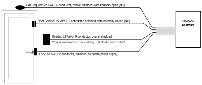
13.0 DOOR TOPOLOGY DIAGRAM
This diagram shows the Lock, Door Contacts, REX and Reader connected to the controller.
|
Connection Type |
Max Distance |
Wire Gauge & Specifications |
|---|---|---|
|
Request to Exit |
500 ft. from controller |
22 AWG; 4-conductor, overall shielded; wired normally open (NO) |
|
Door Contact |
500 ft. from controller |
22 AWG; 2-conductor, overall shielded; wired normally closed (NC) |
|
Lock Hardware |
500 ft. from controller |
18 AWG; 2-conductor minimum, shielded; Separate Power Supply. |
|
Refer to manufacturer’s instructions for device wiring (manufacturer's specs may supersede Galaxy specs). |
||
Jumper-out the following contacts, only if they are unused …
-
DRM board: If door contacts are not installed, you must jumper CNT to GND.
-
CPU board: If Low Battery wiring is not installed, you must jumper Low Batt to GND.
-
CPU board: If AC Fail wiring is not installed, you must jumper the AC Fail to GND.