Hardware Installation
This topic covers Hardware Programming Requirements and Controller Installation Steps for installing the hardware install on the End-User’s site.
FEATURED TOPICS
-
Controller CPU Configuration (via Web or Direct Connect)
Board Programming Requirements
This section lists the requirements and tools you must have to program the controller boards.
-
You will need a Programming Cable and Board Programming Tool (Web Config Tool or Direct Serial Connect) to configure the CPU and daughter boards.
 Connect to 635 CPU using the 635 Web Configuration Tool
You can configure the 635-Series CPU using the Galaxy 635 Web Configuration Tool.
635 CPU Programming
Cable
Connection Requirements
635 Web Config. Tool
(install WCT)Standard Cat5e cable
-
Connect Laptop to 635-CPU at the LAN Port.
-
The Web Config Tool opens in a standard web browser.
-
The Web Config Tool finds the 635-CPUs by MAC address.
-
The CPU must be on same network segment as the Web Config Tool (computer running the tool).
-
The Panel door/tamper switch must be open for detection.
Download the 635 Web Configuration Tool (exe) to configure & test boards.
Also see the Web Configuration Tool Guide (pdf) for information about using the Web Config Tool.
Connect & Configure Boards via Direct Serial Connect (RS-232)
All 600 & 635-series CPU boards can be configured using the RS-232 Direct Connect method.
600/635 CPU Programming
Cable
Connection Options
Terminal Emulator Tool
(e.g., TeraTerm)Standard Serial cable
(RS-232)-
Connect to the 600/635-CPU at the on-board RS-232 Port.
-
If needed, use a USB to RS232 Serial Converter cable
PN 81-1015-00
Find on Galaxy Install Media (usb/iso) X:\\Auxiliary\System Galaxy\FTS635\Factory Test\Teraterm\teraterm-4.87.exe
-
Terminal Emulator session parameters:
-
BAUD Bits per Second = 57,600 KBps
-
Parity = None
-
Data Bits = 8
-
Stop Bits = 1
-
Flow Control = None
-
-
The RS-232 Programming Serial Cable comes with controller enclosure:
-
Cable pin-out must be: Pin 2 to Pin 2, Pin 3 to Pin 3, Pin 5 to Pin 5. (i.e., straight-thru wiring)
-
Cable must have a DB9 female connector on one end and a DB9 male connector on the other end.
-
Connect the programming serial cable to the J4 serial port on the CPU Board and the standard 9-pin serial port on the PC or laptop that is running a Terminal Emulator.
-
Additional Requirements ...
-
-
Each Controller must be set to the correct Cluster ID and must match the SG software programming. However, if you are adding more than one controller, you must configure those in the SG software to match the additional panels.
-
When you are adding hardware for the first Customer in System Galaxy, you may add the first Controller to the first Cluster. You can add additional controllers to the first cluster and one panel may be pre-configured for you. Add additional panels for that customer to the same cluster - or you can add a second cluster if you need to and put additional panels in the additional cluster(s).
-
When you are adding hardware for a different Customerin System Galaxy, you must create a new Cluster for the new customer. Do not mix the hardware programming for Customer 1 with the hardware programming for Customer 2, or Customer 3, and so on. Each Customer’s hardware must be on different Clusters.
-
-
Each Controller must have a unique Unit ID number within the Cluster, as determined by the SG software.
-
The CPU Number should be set to "1".
If a second (dual) CPU board is installed, its CPU number should be set to "2". -
All daughter boards (DPI, DIO, DSI, etc.) must have a unique Board ID within their Unit (controller/panel).
-
Board numbers 1 through 16 are valid for each controller.
-
For 635-DPI(DRM): use onboard DIP switches to set a unique binary address on the data bus.
You must set the DIP switch address before you install the board into the board slot.
-
-
A Unique/Valid IP Address must be used for each 6xx-series controller. This address is typically provided by the IT Department or Internet Service Provider. The IP Address assigned to the controller must have the capability to access the Internet. 6xx-series controllers also support DHCP addressing; however, it is recommended to use static addresses for the stability of the Access Control System.
-
The controllers communicate with the Event Server on the port# that is shown in your Onboarding Document.
-
The Outbound Port must be unblocked at firewalls, routers and switches, etc.
-
Typical "NAT" type routers do not need special configuration, as they allow any/all outbound traffic.
-
-
See the Controller Panel Configuration for steps to configure your panel by Web Connect or by Direct Connect.
Control Panel Installation Steps
This section provides basic, high-level steps to install a controller.
REQUIREMENTS
-
Before you can do this step, you must have the Event Server IP Settings that the controller needs to establish connection to the cloud server are found in the On-boarding Document (PDF) that Galaxy provides.
STEPS
-
Leave the Customer’s Ethernet Network cable disconnected from the CPU until you reach Step #8.
-
Install the 635-CPU in the first slot (farthest from the power supply) in the enclosure.
-
To install each 635-DRM(DPI) board ...
-
Before you install the board, set a valid, unique board ID address using the binary DIP switch. Address 1 - 16 is valid. Each daughter board ID must be unique within the panel.
-
Install DRM boards in the same sequential order as their addresses, with DRM #1 being next to the CPU board.
-
-
Complete all of the field wiring to the card readers, door locks, door position switches and REX request to exit devices. Make sure to install door lock surge suppression diodes correctly.
See the GCS Hardware Installation Manual for details. -
Apply power to the controller panel. The yellow “power” LED should be illuminated on each board.
NOTE: The DRMs and other daughter boards (DIO, DSI, etc.) should come up with their correct IDs based on their DIP-Switch settings. Each board must have a valid, unique ID on the data bus in the panel(no duplicates).
-
Perform a “cold reset” by holding the reset button on the CPU board for fifteen (15) seconds.
-
Connect the Ethernet Network cable to the CPU Board.
-
Configure the CPU and other hardware using the Web Config Tool (instructions below).
-
(optionally) Configure the CPU and hardware using Direct Connect to Serial port (below).
-
After you save the CPU settings, the controller CPU should come up and connect to the Event Service using the settings you configured.
-
-
Now you can import the controller into System Galaxy from the Loop Diagnostics screen. See
Controller CPU Programming
-
Configure the Panel’s CPU with the IP Address, Cluster ID, Unit ID and other information using either a Serial Connection or the 635 Web configuration Tool.
Program CPU with the 635 Web Configuration Tool
This section covers how to program a 635-CPU with the Web Configuration Tool
635 CPU Programming
Cable
Connection Requirements
635 Web Config. Tool
(install WCT)Standard Cat5e cable
-
Connect Laptop to 635-CPU at the LAN Port.
-
The Web Config Tool opens in a standard web browser.
-
The Web Config Tool finds the 635-CPUs by MAC address.
-
The CPU must be on same network segment as the Web Config Tool (computer running the tool).
-
The Panel door/tamper switch must be open for detection.
Download the 635 Web Configuration Tool (exe) to configure & test boards.
Also see the Web Configuration Tool Guide (pdf) for information about using the Web Config Tool.
IMPORTANT: You must save your changes on each Web page by clicking Save or Update. Failure to save changes will cause the panel to loose settings when a power reset occurs.
-
After downloading the Web Config Tool, install it on your computer.
-
It should add a Start up Icon to your Desktop.
-
Computer should be in the same network segment as the panel(s)
-
-
Start the Web Config Tool -
-
it will open in your default browser
-
it should find the controller by MAC address
-
-
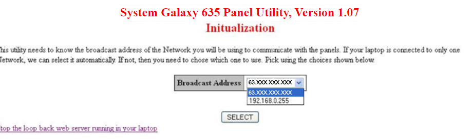
Select the appropriate broadcast IP if your PC has dual NIC cards.
-
Click the serial number for the CPU you wish to configure.
-
Enter the following settings ...
-
Location (optional)
-
CPU network settings that are appropriate for your Customer’s network.
(IP Address, Subnet Mask, and Gateway for the CPU Board.)
-
DO NOT CHANGE THE MAC ADDRESS.
-
Enable the options for ‘Use Default MAC Address’ and Web Server and DHCP.
Network Configuration
Serial Number 3000001 Location Configured IP Address Configured Net Mask Configured Gateway MAC Address Use Default MAC Address Enabled Web Server Enabled DHCP Enabled -
-
Click UPDATE to save your settings to the CPU
-
From the All Panel’s Summary Page, click on the CPU Address of the new panel.
-
Click the Panel Configuration link to finish configuring the CPU.
-
Enter the Cluster ID - must match the cluster in your SG software programming.
-
Enter the Unit ID - must be unique within the Cluster
-
Enter the CPU number “1”
-
Enter the Encryption Passphrase from your Onboarding Document
-
Configure Panel Options and IP Filters as shown in the table below.
-
Enable Event Server 1 and configure the IP Settings.
-
Only configure Event Server 2 if you are providing redundant server support.
Panel Configuration
-
-
Click UPDATE to save the panel changes to the CPU.
-
Open the Panel Status page in your browser and select any daughter board (by serial number) that needs to be configured.
-
Each daughter board must have a unique Board ID on the CPU Data Bus (1-16 is valid).
-
635-series Board IDs are set using the onboard binary DIP Switch.
-
600-series Board IDs can be set via the webpage - you must click Update button to save the new board ID.
-
For Dual section boards, you can configure the use / mode of each section.
-
You must Save (UPDATE) the board configuration when finished.
-
Refer to the Web Config Tool Guide and the 635 Hardware Install Guide for details.
-
-
Once your panel configuration is completed, it can be imported into the System Galaxy software from the Loop Diagnostics screen – see Import New Panels for instructions.
Program CPU with a Direct Serial Connection
600/635 CPU Programming
Cable
Connection Options
Terminal Emulator Tool
(e.g., TeraTerm)Standard Serial cable
(RS-232)-
Connect to the 600/635-CPU at the on-board RS-232 Port.
-
If needed, use a USB to RS232 Serial Converter cable
PN 81-1015-00
Find on Galaxy Install Media (usb/iso) X:\\Auxiliary\System Galaxy\FTS635\Factory Test\Teraterm\teraterm-4.87.exe
-
Connect the serial cable from the PC to the CPU board’s serial port.
-
Launch the TeraTerm Emulator and configure the correct RS232 settings.
-
BAUD = 57,600 KBps
-
Parity = None
-
Data Bits = 8
-
Stop Bits = 1
-
Flow Control = None
TIP: Save your setup for future use.
-
-
Start a new emulator session and select the appropriate COM Port.
-
When the session opens, press the enter key (635 CPU).
(-or in lowercase, type install and enter key (600 CPU)
-
Type config and enter key to begin.
-
Type 0 (zero) and enter key to select CPU board.
-
Type yes (lowercase) and enter key to make changes.
-
Program CPU Network Settings as follows ...
Pressing the enter key will move cursor to each/next field.
-
IP Address. (recommend non-routable when using DHCP)
-
Subnet Mask.
-
Gateway.
-
Encryption passphrase. (from the Onboarding Doc). Enter the passphrase between the equal signs but not the equal signs.
-
Ethernet Speed = 0 (zero)
-
-
Program Panel Options as follows ...
type yes or no (all lowercase)
press enter key (to move cursor to next field)
-
type yes to Enable encryption all traffic
-
type yes to Enable web server
-
type no to Obtain IP Dynamically
-
type no to Extended Card Format
-
-
Program CPU IP Filters as follows ...
-
type yes to Ignore SYN packets
-
type yes to Ignore all BROADCAST packets
-
type yes to Ignore BROADCAST except ARP & GALAXY
-
type no to Use MAC filtering when connected to event server
-
type yes to Send periodic gratuitous ARPs
-
type yes to Ignore UDP packets
-
type no to Protect against denial of service attacks
-
-
Program the Event Server-1 as follows ...
The parameters needed here are found in the Dealer Onboarding Document.
Event Server IP: [ Event Sever-1 IP Address ]
Remote TCP Port: [ Event Server Remote Port ]
Local TCP Port: [ 300X ] < e.g., 3001 or higher*
* Where the number ‘X’ should match the panel Unit ID.
-
type yes to configure Event Server-1
-
press enter key to move cursor to each field, as needed:
-
enter the IP Address + for Event Server-1
-
enter the remote port number for the Event Server
-
enter the panel local port number = 300X (or higher) to match Unit ID.
EXAMPLE: Set local port number based on panel Unit ID.
If the Unit ID =“1” then set the local port to “3001” – set the local port for each panel to that panel’s Unit ID ...-
Panel-1: Unit ID = 1 / local port = 3001
-
Panel-2: Unit ID = 2 / local port = 3002
-
Panel-3: Unit ID = 3 / local port = 3003
-
-
-
-
Press enter key to advance to Event Server-2 ...
-
type yesonly if you are adding a redundant server (yellow highlight in Onboarding Doc).
-
press enter key to move cursor to configure each field, as needed:
-
enter the IP Address + for Event Server-2 IF it is provided in Onboarding Doc.
-
enter the remote port number for the Event Server
-
enter the panel local port number = 300X (or higher) to match Unit ID.
EXAMPLE: Set local port number based on panel Unit ID.
If the Unit ID =“1” then set the local port to “3001” – set the local port for each panel to that panel’s Unit ID ...-
Panel-1: Unit ID = 1 / local port = 3001
-
Panel-2: Unit ID = 2 / local port = 3002
-
Panel-3: Unit ID = 3 / local port = 3003
-
-
-
-
Press the enter key to skip remaining redundant servers.
-
At the final prompt, type yes to save changes to permanent memory.
CHANGE OR CORRECT SETTINGS: If you need to change or correct any settings, simply reissue the config/0 command and use the enter key to skip (hop) down to the field you need to change. Remember to type yes to save changes to permanent memory.
IMPORTANT: You must save your changes to permanent memory. Failure to save changes will cause the panel to lose its settings in the future when a power reset occurs.
RETURN TO THE SAVE PROMPT: If you skipped the “save prompt”, you must retype the config/0 command to return to the save prompt. Using the enter key, you can skip (hop) through the data fields you already programmed. When you reach the save prompt again, you can type yes as required.
-
Since your CPU is configured, you can configure daughter boards using the Panel webpage.
Open the Panel Status page in your browser by typing the IP Address into a browser and select any daughter board (by serial number) that needs to be configured.
-
Each daughter board must have a unique Board ID on the CPU Data Bus (1-16 is valid).
-
635-series Board IDs are set using the onboard binary DIP Switch.
-
600-series Board IDs can be set via the webpage - you must click Update button to save the new board ID.
-
For Dual section boards, you can configure the use / mode of each section.
-
You must Save (UPDATE) the board configuration when finished.
-
Refer to the Web Config Tool Guide and the 635 Hardware Install Guide for details.
-
-
Once your panel configuration is completed, it can be imported into the System Galaxy software from the Loop Diagnostics screen – see Import New Panels for instructions.
-
-
Verify that your new controller is connected in System Galaxy software ...
-
Update the controller to the latest (flash) firmware as needed – The CPU must run the flash version that is compatible with the System Galaxy software.
-
Begin loading flash by right-clicking on the appropriate Cluster icon in the SG Hardware Tree, choose ‘Load’. The GCS Loader window will open. You can select the individual controller and send a ‘Get Controller Info’ command.
-
You can find the compatible Flash version in the Help About screen from the SG menu.
-
-
Also Load Data to the controller with the current database information from the GCS Loader window.
-
Continue with normal programming.
Notes / Best Practices:
-
Two surge suppression diodes are included with each 635 DRM board. It is imperative that a diode is installed at each locking device - as close to the lock as possible - for stable operation.
-
Magnetic locks ("maglocks") typically contain their own surge suppression circuitry, and do not require a diode. All other devices - including relays and contactors - should have a diode installed.
-
Locking hardware designed to operate on AC or DC voltage source may contain a bridge rectifier within the wiring harnes. This component should be removed when the lock is used with DC voltage sources - it impairs the effectiveness of the diode.
-
The use of AC powered locking devices is not recommended.
-
The proper configuration of the network filter options is necessary for stable operation. These filters are completely disabled when the controller door is open! For this reason, you must verify that the tamper switch is correctly wired, and that the controller door closes properly. If you are not using a tamper switch, the tamper input should be jumpered to ground.
-
If you are not using door contacts, you should jumper the door status input (CNT) to ground (COM). Failure to due so will result in alarm events, and adversely affects the behavior of the reader LED.
NEXT STEPS